Call us: +91-9000909051, 9963455557
Email us : redandbluefiresafety@gmail.com
Red and Blue Fire SystemsRed and Blue Fire SystemsRed and Blue Fire SystemsRed and Blue Fire Systems
  • Home
  • About Us
  • Products
    • Fire Extinguishers
    • Sprinklers
    • Conventional and Addressable Fire alarm System
    • Fire Fighting System
    • CCTV
    • Hydrant Valve
  • Services
  • Gallery
  • Contact us

Conventional Panels

    Home Conventional Panels

    RE-104

    re104
    • Specifications
    • Features

     AC Power

    220 VAC, 50 Hz. +10% – 15%

    Battery(Lead Acid only)

    Charging: Constant Voltage – 27.6v @ 0.5A(Max)

    Charging Capacity: 7 Amp Hour Battery Max.

    System Quiescent Current: 60mA

    Initiating Device Circuits (Zone Circuit)

    All zones are Class B wiring

    Normal Operating Voltage: Nominal 24 VDC

    Alarm Current: 15 – 35mA threshold

    Short Circuit Current: 42mA Maximum

    Loop resistance: 50 ohms Maximum

    End-Of-Line Resistor: 4.7K, 1/4watt

    Standby Current: 6.8mA (2.4mA for Detectors)

    • As per IS -2189 Standard.
    • Rugged CRCA sheet with powder coated finish.
    • Standby battery backup with built in charging.
    • Fire / Fault status in unambiguous colored LED indication.
    • Switch Mode Power Supply.
    • Tactile Keypad for easy panel operation.
    • System on indication.
    • Main, Standby status indication.
    • Low Battery visual warning with audible tone.
    • Relay output for actuators for Fire and Fault.
    • Lamp Test facility
    • Zone wise one man walk Test Facility.
    • Zone wise Isolation facility with loop voltage cut off.
    • Compatible to all type of Conventional Detectors.

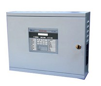
    RE-102

    re102
    • Specifications
    • Features

     AC Power

    220 VAC, 50 Hz. +10% – 15%

    Battery(Lead Acid only)

    Charging: Constant Voltage – 27.6v @ 0.5A(Max)

    Charging Capacity: 7 Amp Hour Battery Max.

    System Quiescent Current: 60mA

    Initiating Device Circuits (Zone Circuit)

    All zones are Class B wiring

    Normal Operating Voltage: Nominal 24 VDC

    Alarm Current: 15 – 35mA threshold

    Short Circuit Current: 42mA Maximum

    Loop resistance: 50 ohms Maximum

    End-Of-Line Resistor: 4.7K, 1/4watt

    Standby Current: 6.8mA (2.4mA for Detectors)
    • As per IS -2189 Standard.
    • Rugged CRCA sheet with powder coated finish.
    • Standby battery backup with built in charging.
    • Fire / Fault status in unambiguous colored LED indication.
    • Switch Mode Power Supply.
    • Tactile Keypad for easy panel operation.
    • System on indication.
    • Main, Standby status indication.
    • Low Battery visual warning with audible tone.
    • Relay output for actuators for Fire and Fault.
    • Lamp Test facility
    • Zone wise one man walk Test Facility.
    • Zone wise Isolation facility with loop voltage cut off.
    • Compatible to all type of Conventional Detectors.

    RE-2504

    RE2504
    • Specifications
    • Features

     Primary Power – CN1 (RE-SMPS-4A-R1)

    220VAC ± 10%, 50 Hz, 2.5Amps.

    Standby Power – CN10

    24v D.C (2 Nos of 12v, 12Ah Sealed Lead acid battery).

    Operating Condition

    Operating Temperature – 15 – 25° C/60-77° F.

    Relative Humidity – 93 ± 2% RH (non-condensing) at 25 ±2° C/77 ±3° F.

    Charging Circuit

    Charging Voltage – 28.4V, ±0.2V

    Charging Current – 800mA (Max.).

    Initiating Device Circuits – CN 8

    All zones are Class B Style B/C operation (Programmable).

    Normal Operating Voltage: 14 – 21 VDC.

    Alarm Current: 15 – 30mA.

    Short Circuit Current: 45mA Maximum.

    Loop resistance: 100 ohms Maximum.

    End-Of-Line Resistor: 3K9, 1/2watt

    Standby Current: 7mA (2mA for Detectors)

    •  4/8 Class B initiating device circuit (IDC).
      •  All zones accept smoke detectors and any normally open contact device.
      •  Any Zone can be configured as Alarm or supervisory Zone.
    •  2 Class B Notification Appliance Circuits (NAC).
    •  Fully complies with UL -864 and NFPA-72.
    •  Rugged CRCA sheet with powder coated finish.
    •  Operates on 220v 50Hz, AC Mains power supply.
    •  Standby (battery) backup 24v DC power supply with built in charger.
    •  Error free Fire / Fault status in unambiguous colored LED indication.
    •  Main, Standby status audible and visual indication.
    •  Battery Low visual warning with audible tone.
    •  Form-C relays for fire, fault and supervisory.
    •  Zone Isolation facility with loop voltage cut off.
    •  Ground fault annunciation facility at 0 ohms.
    •  All field wiring circuits are Power limited except 220v A.C. and Battery.
    •  All field wiring circuits are supervised.
    •  AC Low voltage cutoff.
    •  Programmable NAC’s.
    •  Programmable IDC’s.
    •  Programmable AC loss delay.
    •  Alarm verification facility.
    •  Programmable Trouble reminder facility.
    •  Events history with RTC.

    RE-2554

    RE2554
    • Specifications
    • Features

     AC Power

    220 VAC, 50 Hz. +10% – 15%

    Battery(Lead Acid only)

    Charging: Constant Voltage – 27.6v @ 0.5A(Max)

    Charging Capacity: 7 Amp Hour Battery Max.

    System Quiescent Current: 60mA

    Initiating Device Circuits (Zone Circuit)

    All zones are Class B wiring

    Normal Operating Voltage: Nominal 24 VDC

    Alarm Current: 15 – 35mA threshold

    Short Circuit Current: 42mA Maximum

    Loop resistance: 50 ohms Maximum

    End-Of-Line Resistor: 4.7K, 1/4watt

    Standby Current: 6.8mA (2.4mA for Detectors)

    • Fully complies with UL -864 and NFPA-72.
    • Rugged CRCA sheet with powder coated finish.
    • Operates on 120 – 220v 50 /60 Hz, AC Mains power supply.
    • 16×2 Dot Matrix LCD Display.
    • 4/8 Class B initiating device circuit (IDC).
      • All zones accept smoke detectors and any normally open contact device.
      • Any Zone can be configured as Alarm or supervisory Zone.
    • 2 Class B Notification Appliance Circuits (NAC).
    • Standby (battery) backup 24v DC power supply with built in charger
    • Error free Fire / Fault status in unambiguous colored LED indication.
    • System ON indication.
    • Main, Standby status audible and visual indication.
    • Battery Low visual warning with audible tone.
    • FormC relays for fire, fault and supervisory.
    • Resettable / uninterrupted 24v D.C. Output. ? RS 485 Communication facility (Optional).
    • Lamp Test facility.
    • All field wiring circuits are Power limited except 120 – 220v AC and Battery.
    • All field wiring circuits are supervised.
    • Walk Test facility.
    • Zone Isolation facility with loop voltage cut off.
    • Earth fault annunciation facility at 0 ohms. AC Low voltage cutoff.

    RE-2508

    RE2508
    • Specifications
    • Features

    Primary Power – CN1 (RE-SMPS-4A-R1)

    220VAC ± 10%, 50 Hz, 2.5Amps.

    Standby Power – CN10

    24v D.C (2 Nos of 12v, 12Ah Sealed Lead acid battery).

    Operating Condition

    Operating Temperature – 15 – 25° C/60-77° F.

    Relative Humidity – 93 ± 2% RH (non-condensing) at 25 ±2° C/77 ±3° F. Charging Circuit

    Charging Voltage – 28.4V, ±0.2V

    Charging Current – 800mA (Max.).

    Initiating Device Circuits – CN 8

    All zones are Class B Style B/C operation (Programmable).

    Normal Operating Voltage: 14 – 21 VDC.

    Alarm Current: 15 – 30mA.

    Short Circuit Current: 45mA Maximum.

    Loop resistance: 100 ohms Maximum.

    End-Of-Line Resistor: 3K9, 1/2watt

    Standby Current: 7mA (2mA for Detectors)

    • 4/8 Class B initiating device circuit (IDC).
      • All zones accept smoke detectors and any normally open contact device.
      • Any Zone can be configured as Alarm or supervisory Zone.
    • 2 Class B Notification Appliance Circuits (NAC).
    • Fully complies with UL -864 and NFPA-72.
    • Rugged CRCA sheet with powder coated finish.
    • Operates on 220v 50Hz, AC Mains power supply.
    • Standby (battery) backup 24v DC power supply with built in charger.
    • Error free Fire / Fault status in unambiguous colored LED indication.
    • Main, Standby status audible and visual indication.
    • Battery Low visual warning with audible tone.
    • Form-C relays for fire, fault and supervisory.
    • Zone Isolation facility with loop voltage cut off.
    • Ground fault annunciation facility at 0 ohms.
    • All field wiring circuits are Power limited except 220v A.C. and Battery.
    • All field wiring circuits are supervised.
    • AC Low voltage cutoff.
    • Programmable NAC’s.
    • Programmable IDC’s.
    • Programmable AC loss delay.
    • Alarm verification facility.
    • Programmable Trouble reminder facility.
    • Events history with RTC.

    RE-2558

    re2558
    • Specifications
    • Features

     AC Power

    220 VAC, 50 Hz. +10% – 15%

    Battery(Lead Acid only)

    Charging: Constant Voltage – 27.6v @ 0.5A(Max)

    Charging Capacity: 7 Amp Hour Battery Max.

    System Quiescent Current: 60mA

    Initiating Device Circuits (Zone Circuit)

    All zones are Class B wiring

    Normal Operating Voltage: Nominal 24 VDC

    Alarm Current: 15 – 35mA threshold

    Short Circuit Current: 42mA Maximum

    Loop resistance: 50 ohms Maximum

    End-Of-Line Resistor: 4.7K, 1/4watt

    Standby Current: 6.8mA (2.4mA for Detectors)

    • Fully complies with UL -864 and NFPA-72.
    • Rugged CRCA sheet with powder coated finish.
    • Operates on 120 – 220v 50 /60 Hz, AC Mains power supply.
    • 16×2 Dot Matrix LCD Display.
    • 4/8 Class B initiating device circuit (IDC).
      • All zones accept smoke detectors and any normally open contact device.
      • Any Zone can be configured as Alarm or supervisory Zone.
    • 2 Class B Notification Appliance Circuits (NAC).
    • Standby (battery) backup 24v DC power supply with built in charger
    • Error free Fire / Fault status in unambiguous colored LED indication.
    • System ON indication.
    • Main, Standby status audible and visual indication.
    • Battery Low visual warning with audible tone.
    • FormC relays for fire, fault and supervisory.
    • Resettable / uninterrupted 24v D.C. Output. ? RS 485 Communication facility (Optional).
    • Lamp Test facility.
    • All field wiring circuits are Power limited except 120 – 220v AC and Battery.
    • All field wiring circuits are supervised.
    • Walk Test facility.
    • Zone Isolation facility with loop voltage cut off.
    • Earth fault annunciation facility at 0 ohms. AC Low voltage cutoff.

    RE-700

    re700
    • Specifications
    • Features

    AC Power

    220 VAC, 50 Hz, +10%, -15%.

    Wire size: 1.5 Sq. mm with 600 V insulation

    Battery (Lead Acid only)

    Charging Current: Constant Voltage – 27.6v @ 0.8A (Max.).

    Charging Capacity: 7 Amp Hour Battery (Higher size are request).

    System Quiescent Current: 50mA + (4.4 – 6.8mA per zone)

    Initiating Device Circuits (Zone Circuit)

    All zones are Class B operation

    Normal Operating Voltage: Nominal 24 VDC

    Alarm Current: 15 – 35mA threshold

    Short Circuit Current: 40mA Maximum

    Loop resistance: 100 ohms Maximum

    End-Of-Line Resistor: 4.7K, 1/4watt

    Standby Current: 8.2mA (4mA for Detectors)

    Notification Appliance Circuits (Sounder Circuit)

    Class – B wiring

    Operating Nominal Voltage: 24 VDC

    Current for all NACs: 0.2A per Zone

    End-Of-Line Resistor: 4.7K, 1/4watt

    • Fully complies with IS 2189: 1988.
    • Rugged CRCA sheet with powder coated finish.
    • 20 X 4 LCD Dot Matrix Display.
    • 12 – 128 Class B initiating device circuit (IDC / Zone Circuits).
    • One Class B Notification Appliance Circuits (NAC / Sounder).
    • Low Battery / Warning audio / Visual Display.
    • Operates on 220v, AC Mains power supply.
    • Standby (battery) back up 24v DC power supply with built in charger.
    • Operates on 48V DC (Without Battery Backup) (Optional).
    • Error free Fire / Fault status in unambiguous colored LED indication.
    • Main, Standby status with visual/audible indication.
    • Battery Low visual warning with audible tone.
    • Event storage with RTC. ?Form C relays for Fire and fault.
    • RS 485 and RS 232 Communication Facility.
    • TCP/IP (Optional) facility.
    • Walk Test facility.
    • Zone Isolation facility with loop voltage cut off.
    • Zone loops with Zener Barrier. (Optional). Compatible with all types of conventional detectors, Pull Stations and
    • any normally open contact devices. Zonewise Sounder & Relay Output (Optional).

    RE-150D

    re150d
    • Specifications
    • Features
    1. . Power Supply:
      1. AC Input Supply : 230 V AC, 50Hz
      2. DC Input Supply : 24 V DC o
    2.  Operating Conditions : -10 to 45 C, 95 % RH Max.
    3. Operating Voltage : 24 V DC
    4. Normal Loop Voltage : 20.7 DC
    5. Open Threshold Current : 4.2 mA
    6. Short Circuit Threshold Current : 40 mA
    7. Stand by Threshold Current ( EOL Current + detector’s Current): 8.2 mA
    8. Alarm Current : 20 – 35 mA
    9. Quiescent Current : 50mA Plus 4.2mA per Zone
    10. Colour of the Panel : Semains Gray (Red, Red Texture – optional)
    11. ALARM OUTPUT: Standard Common Output : 0.2A per Zone.
    12. REMOTE INDICATION OUTPUTS: Outputs : Fire Relay Contacts (230 V 2A contact).
    • Fully confirms IS 2189: 1988
    • 16SWG Rugged CRCA with powder coated finish.
    • Modular construction.
    • Operates on 230V, A.C supply.
    • Battery backup with built in charging.
    • 16×2 LCD Dot matrix Display.
    • Fire / Fault status in unambiguous coloured LED indication.
    • Low battery / battery fail warning audio / visual indication.
    • A.C fail audio / visual warning.
    • Charger fail audio / visual warning
    • System on, AC on, Battery on & Charger on indications
    • Potential Free Relay Contacts for actuators.
    • Lamp test facility.
    • One man walk test facility.
    • Compatible to all types of conventional detectors.
    • Twin RED LED indication for fire.
    • Zone Isolation facility with loop voltage cut off.
    • Earth Fault with Audio and Visual Indications. Supervised Sounder 24

    RE-15AR

    re15ar
    • Specifications
    • Features

    Primary Power (RE-SMPS-4A-R1)

    120 – 220VAC ± 10%, 50 Hz, 2.5Amps.

    Standby Power

    24v D.C (2 Nos of 12v, 12Ah Sealed Lead acid battery).

    Operating Condition

    Operating Temperature: 0 – 49° C/32-120° F.

    Relative Humidity: 93 ± 2% RH (non-condensing) at 25 ±2° C/77 ±3° F.

    Charging Circuit

    Charging Voltage: 28.4V, ±0.2V With current 800mA (Max).

    ID.C. Output Power

    Supervised 24VDC regulated, 1A Max. (for 4 wire smoke detector)

    Common Four Form C Relays

    Relay Contact Rating: 2Amps @ 30 VDC, 2Amps @ 30VAC.

    Power Factor: 0.6

    • Complies with UL -864 and NFPA-72.
    • Rugged CRCA sheet with powder coated finish.
    • Operates on 120-220v 60 / 50 Hz, A.C. Mains power supply.
    • Standby (battery) backup 24v D.C. power supply with built-in charger
    • 16×2 Dot Matrix LCD Display.
    • 4 Class – B / 2 Class – A Initiating device circuits (I.D.C).
      • All zones accept smoke detectors and any normally open Contact device.
      • Any Zone can be configured as Alarm or supervisory Zone.
    • 2 Class – B Releasing Agent Circuits (R.A.C).
    • 2 Notification Appliances Circuits (N.A.C).
    • Error free Fire / Fault status in unambiguous colored LED indication.
    • System ON indication.
    • Main, Stand-by status audible and visual indication.
    • Battery Low visual warning with audible tone.
    • 4 Form c programmable relay for fire/fault/supervisory/pre-release/release.
    • 100 Events Log with RTC. 4 Programmable Input circuits for manual release /Abort/Pressure Switch/Actuator low ?pressure.
    • Zone Isolation Facility.
    • Walk test Facility.
    • All Wiring Circuits are supervised.
    • Earth Fault annunciation facility
    • All Field Circuits are power limited except 120-220v AC and Battery.
    • RS 485 Communication Facility (Optional for Zone wise contact / MODBUS). Two Modes of Operation (Auto /Manual).

    RE-25AR

    re25ar
    • Specifications
    • Features

    Primary Power (RE-SMPS-4A-R1)

    120 – 220VAC + 10% -15%, 60 / 50 Hz, 2.5Amps.

    Standby Power

    24v D.C (2 Nos of 12v, 12Ah Sealed Lead acid battery).

    Operating Condition

    Operating Temperature – 0 – 49° C / 32 – 120° F.

    Relative Humidity – 93 ± 2% RH (non-condensing) at 32 ±2° C/95 ±3°F.

    Charging Circuit

    Charging Voltage – 28V, ±0.5V

    Charging Current – 800mA (Max.).

    Initiating Device Circuits – CN11

    All zones are Class B Style B/C operation (Programmable).

    Normal Operating Voltage: 14 – 21 VDC.

    Alarm Current: 15 – 30mA.

    Short Circuit Current: 45mA Maximum.

    Loop resistance: 100 ohms Maximum.

    End-Of-Line Resistor: 3K9, 1/2watt

    Standby Current: 7mA (2mA for Detectors)

    Note: For compatible devices refer Chapter 9(CD 01).

    • Fully complies with UL -864 and NFPA-72
    • Rugged CRCA sheet with powder coated finish.
    • 16×2 Dot Matrix LCD Display.
    • Operates on 120-220v 60 / 50 Hz, AC Mains power supply.4 Class B initiating device circuit (IDC).
    • All zones accept smoke detectors and any normally open Contact device.
    • Any Zone can be configured as Alarm or supervisory Zone.
    • 2 Class B Releasing Agent Circuits (RAC).
    • 2 Class B Notification Appliance Circuits (NAC).
    • Standby (battery) backup 24v DC power supply with built in charger
    • Error free Fire / Fault status in unambiguous colored LED ?indication.
    • System ON indication.
    • Main, Standby status audible and visual indication.
    • Battery Low visual warning with audible tone.
    • 3 Form C programmable relays for Fire / fault / ?supervisory / Gas Released.
    • Programmable two Input Circuits for Manual release and Abort.
    • Two modes of operations Auto / Manual.
    • Programmable 24v D.C Outputs.
    • RS 485 Communication facility (Optional).
    • MODBUS (Optional).
    • Events history log with RTC.
    • Walk Test facility.
    • Zone Isolation facility.
    • Earth fault annunciation facility.
    • All field wiring circuits are Power limited except 220v AC and Battery.
    • All field wiring circuits are supervised.
    • AC Low voltage cutoff. Alarm verification facility .
    • Fully complies with UL -864 and NFPA-72.

    RE-120GR

    re120gr
    • Specifications
    • Features

    Power

    220-240 VAC, 50 Hz.

    Wire size: 1.5 Sq. mm with 600V insulation

    Battery (Lead Acid only)

    Charging Voltage: 27.9 VDC.

    Charging Current: 1.2Amps (Max) S

    ystem Quiescent Current: 80mA + (2.4mA for Detectors)

    Initiating Device Circuits (Zone Circuit)

    All zones are Class B wiring

    Normal Operating Voltage: Nominal 24 VDC

    Alarm Current: 15 35mA threshold

    Short Circuit Current: 40mA Maximum

    Loop resistance: 50 ohms Maximum

    End-Of-Line Resistor: 4.7K, 1/4watt

    Standby Current: 6.8mA (2.4mA for Detectors)

    Notification Appliance Circuits (Sounder/Hooter Circuit)

    Operating Nominal Voltage: 24 VDC

    Hooter (NACs) output: 0.5A (Each)

    End-Of-Line Resistor: 4.7K, 1/4watt

    • Rugged CRCA sheet with powder coated finish.
    • Operates on 220V, A.C supply
    • Battery backup with built in charging.
    • 16 X 2 LCD Dot Matrix Display.
    • Evacuate and Key pad Enable, Disable Facility.
    • Low battery visual warning with audible tone.
    • Relay output for actuators.
    • Remote fire indication with Audible Tone.
    • Compatible to all types of conventional detectors.
    • Zone Disable (Isolation) facility with loop voltage cut off.
    • Resettable 24v DC output for 4 wire detectors (Optional).
    • Three 24V Hooter Output (Fire, after Cross zone, after gas release).
    • Two mode operation facility (Auto / Manual).
    • Programmable FAP input selection Facility.
    • Programmable Solenoid Output with On and OFF Timer.
    • Main / Standby Cylinder output Facility (Optional).
    • Programmable Standby output.
    • Gas Inhibition and Instant release facility.
    • Manual Gas Release with or without timer.
    • Actuator pressure low sensing facility.
    • Pressure switch facility

    RE-127

    re127
    • Specifications
    • Features

    AC Power :

    120-220 VAC,60/ 50 Hz

    Operating Condition

    Operating Temperature : 0 – 49° C/32-120° F.

    Relative Humidity : 93 ± 2% RH (non-condensing) at 25 ±2° C/77 ±3° F.

    Notification Appliance Circuits (Sounder/Hooter Circuit)

    Operating Nominal Voltage: 24 VDC

    Sounder (NAC) output: 0.5A

    End-Of-Line Resistor: 4.7K, 1/4watt

    Rs485 Communication Port

    Max. Distance: 1.2 Km Max. (Use CAT5E or Equivalent Cable)

    Potential Free Contact

    1 No Fire Contact (2A@30VDC / 0.5A@125VAC)

    • Operates on 120 to 220V AC, 60 / 50 Hz.
    • 20 X 4 Characters LCD display.
    • Repeats all the indication / Information of main panel.
    • RS 485 Communication for Standalone / Network Repeater.
    • System ON, AC ON, Battery ON, Charger ON indications.
    • Alphanumeric keypads.
    • Sounder (Evacuate) test facility.
    • Lamp test facility.
    • RE-127R, RE-127M Compatible with RE-2558, RE-2554, RE-700.
    • RE-127GR Compatible with RE-120GR, RE-25AR.
    • Passive / Active Programmable (RE-127M).
    • Networkable Maximum 16 panels (RE-127R, RE-127M)

    Contact us

    #30-5-6,1st Floor koka Chalapathirao Street, Near Vijaya Talkies Centre Eluru Road , Vijayawada- 520002. Cell: 9000909051, 9963455557 E-mail: redandbluefiresafety@gmail.com

    Red and Blue Fire Safety Systems

    Located At

    Copyright 2015 Red and Blue Fire Systems | All Rights Reserved
    • Home
    • About Us
    • Products
      • Fire Extinguishers
      • Sprinklers
      • Conventional and Addressable Fire alarm System
      • Fire Fighting System
      • CCTV
      • Hydrant Valve
    • Services
    • Gallery
    • Contact us
    Red and Blue Fire Systems